Turning a project into a product
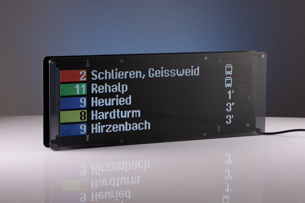
A step by step account of how I turned a project of mine into a polished product that will be available for purchase over at stationdisplay.com.
Introduction
As some of you may know I built this LED sign a while back. There was quite a bit of feedback and questions as to where one can buy their own. Initially I indicated that I will not be making a product as I know the amount of work involved may not be worth my time.
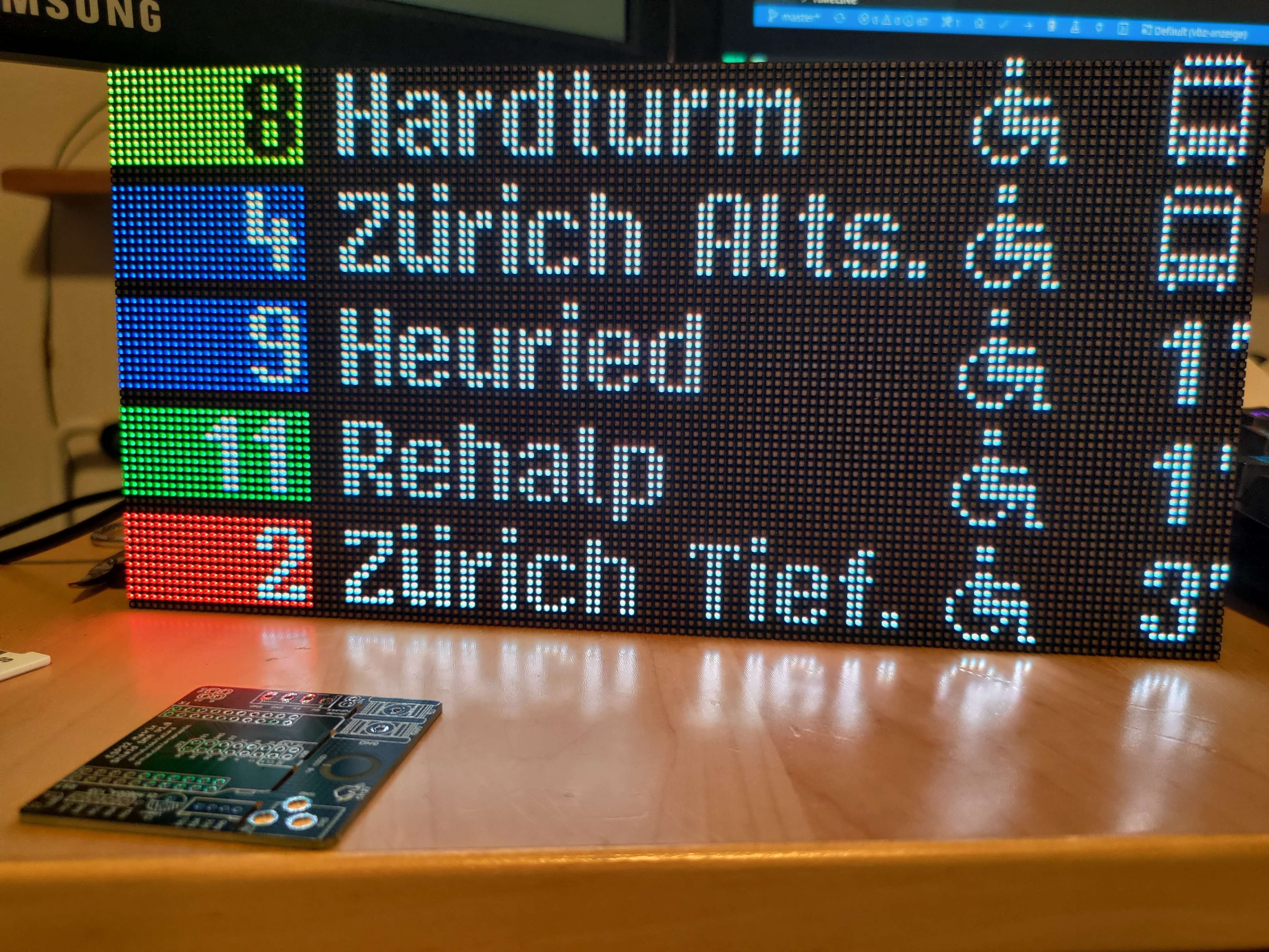
However I changed my mind as I had some ideas about what changes I could make to make this a more solid product that won’t require me to spend hours providing support.
Additionally I decided to make a very limited run initially to see if there is any interest to actually purchase it. Other than my time, the cost is to develop this further is reasonable and I spend a lot of time on projects anyways which this is very similar too.
Analyses of changes required
The biggest reason I initially did not want to sell this was the fragility of the LED display. Without a case the display is extremely fragile and you can easily knock of a 1515 LED.
I compiled the following list of what I definitely had to change:
- The LEDs need a case, they are too fragile for a product without
- All electronics need to be contained in the device
- The current data source has request limits and requires an API key. I can’t have the customer go through hoops to get an API key and configure it
- Wifi needs to be configured on the device. Currently, first start of the device makes an AP to which you connect and then via a webserver you setup your wifi
- I don’t want a customer needing to compile and flash firmware
- Currently configuration is done via the webserver on the device as well. That is too complex IMO
- Picking the station you want to display requires the look up of an ID in a large excel sheet.
- Usability for a non-tech person is non-existent
Getting started
The case
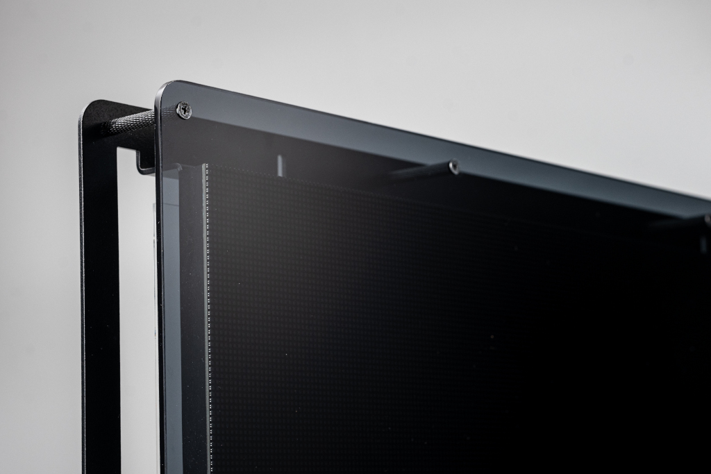
A case was a must requirement to protect the LEDs. You can easily nock them off and soldering them is difficult.
I spent a lot of time on this because I wanted to do something that would not turn my project into a cost sinkhole. 3D printing was out of the question because of the size. Building something out of wood seemed also overly complex. Injection molding was definitely out of the question for such a small run.
I wanted something that look modern, stylish and could be considered a “smart” piece of artwork.
So I decided I would try to construct something out of a single piece of folded aluminum. There is a local company Blexon which I have used previously for my 3d printer as well as a cyberdeck and they have a very cool online portal where you can get an instant quote after you upload your file. They newly added powder coating which would be perfect to give my project a more production feel than bare aluminum.
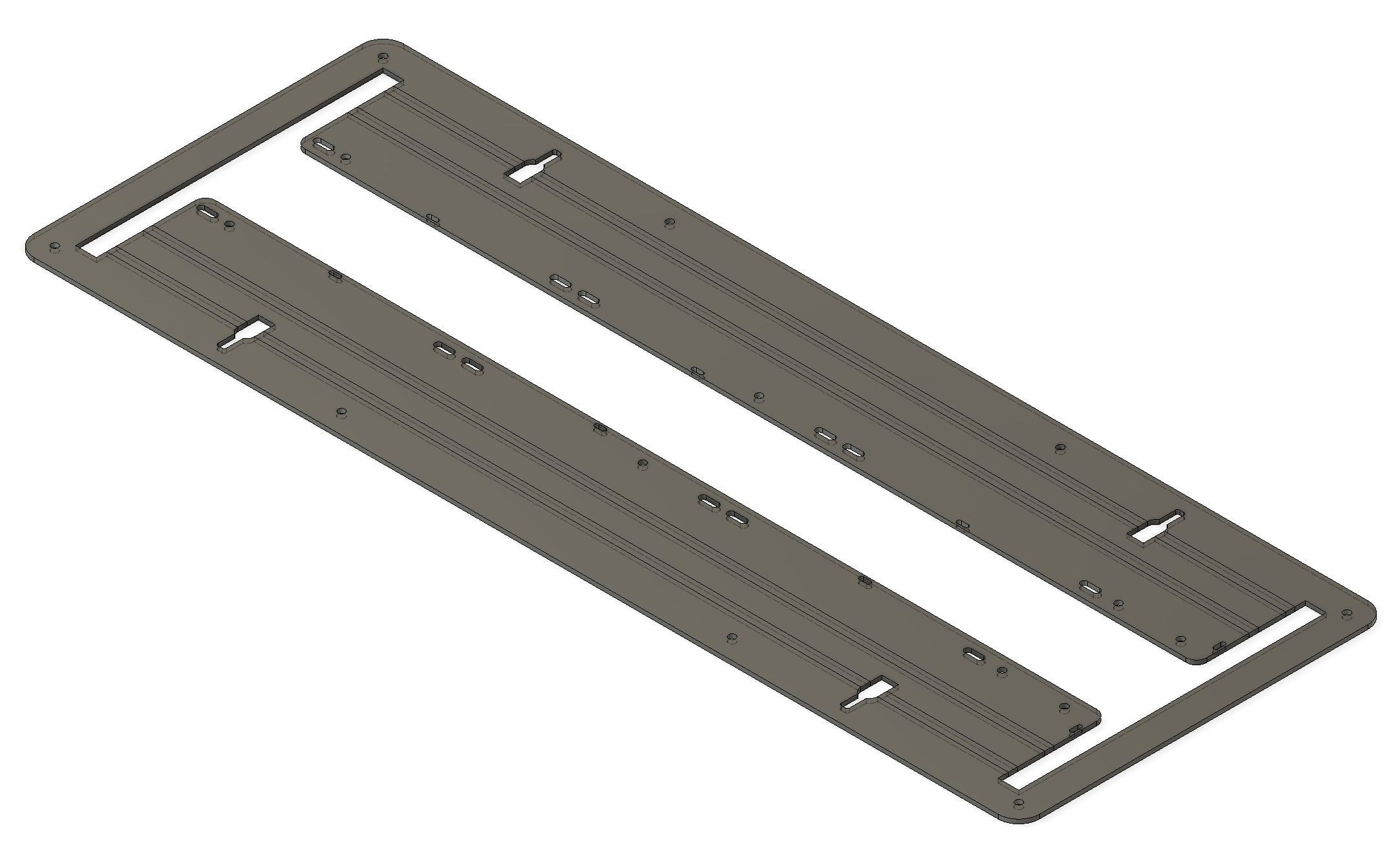
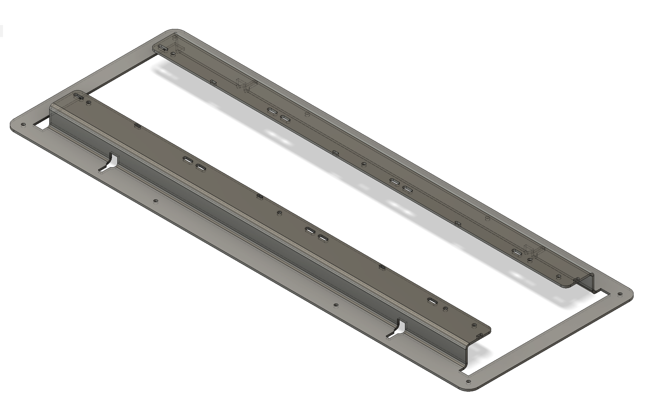
I went through quite a few iteration in Fusion 360 until I found one that would work and can actually be manufactured. There are a lot of limitations to how tight a bend can be and still be manufactured. I also added holes for tying down cables, holes for hanging and a hole for cable strain relieve.
After a lot of double checking as the production of a single frame isn’t cheap (setup costs are high) I sent it to Blexon and received the finished aluminum piece a week later. I did not have this test version powder coated as it would have added a lot of cost.
The frame fit perfectly and I was able to mount the LED panels.
To protect the LED I decided on a darkened piece of Plexiglass that would mount in front of the LED panels. I had this done by ABC Kunststoff-Technik GmbH which is a local place that does all kinds of Plexiglass work and also has an online portal for ordering/pricing.
Later I also added a piece of Plexiglass on the back to protect the electronics.
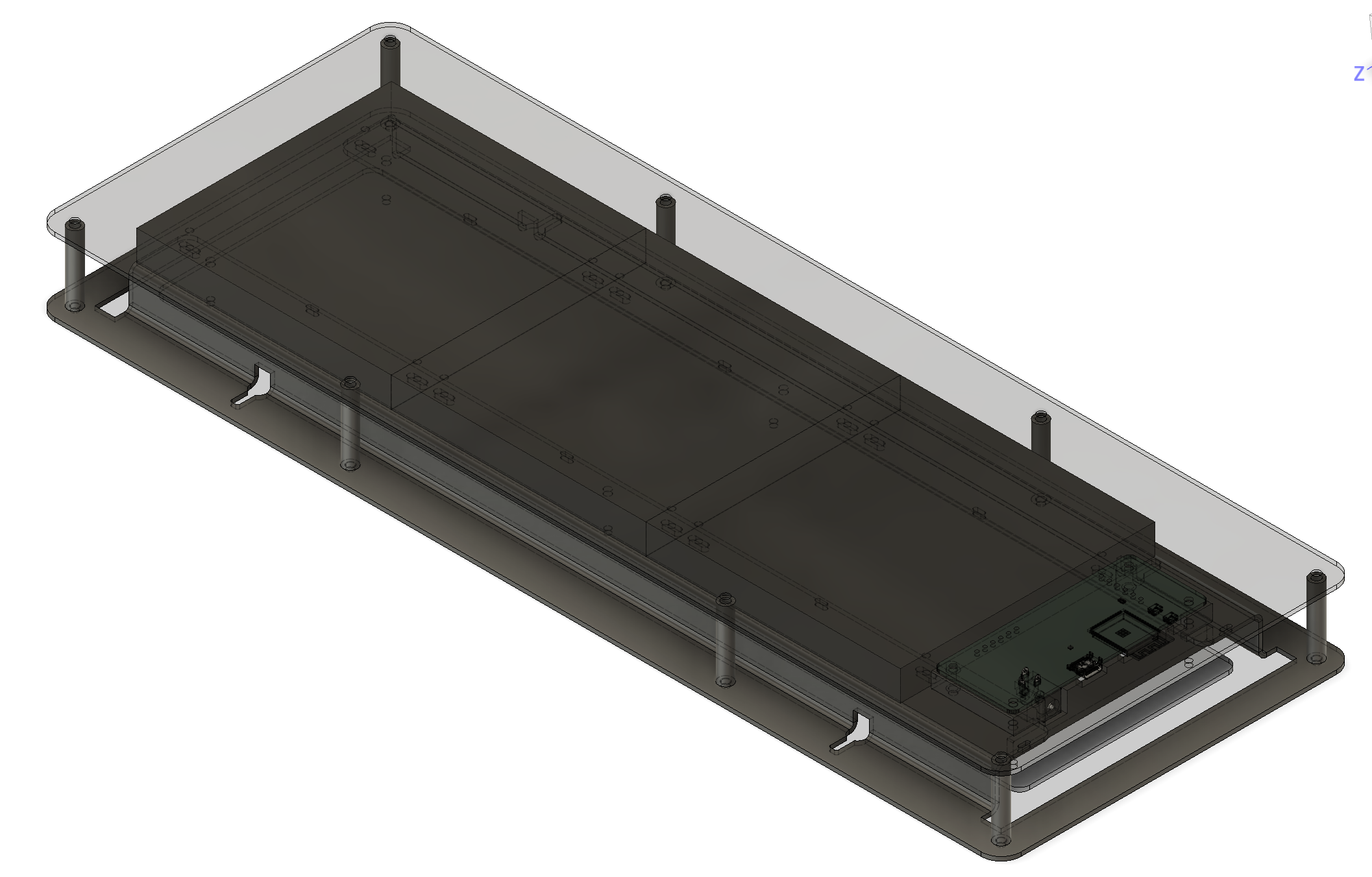
The LED panels
The project used a 128 x 64 pixel P2.5 LED panel. This was however too short for me to represent what the original panel that you see on the street shows which is 196 x 56. I ordered some 64 x 64 panels to test having them chained and they worked well.
![]()
The next challenge was to acquire a large quantity of these with the same chipset and mounting holes as I did not want to have to re-order different frames depending on what LEDs I received. Thankfully I was able to find a vendor via AliExpress that could help me and could also guarantee the mounting and chipset. Additionally they can give me a 1 year warranty on the panels which is better than nothing but I have to provide 2 years here in Switzerland.
The PCB
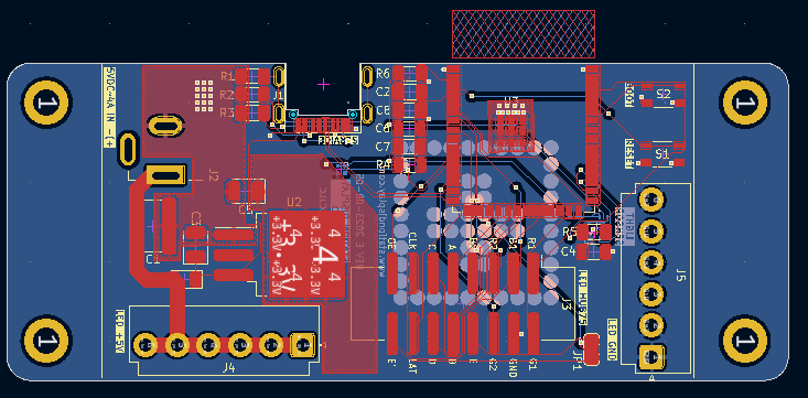
The PCB wasn’t a big challenge although it was the first project I did with an ESP32-S3 instead of an ESP32-S2. This removed a lot of components that I usually had to add like USB controller etc. which made everything much simpler. In the end I did go through 5 iterations of the PCBs until the final version.
Some points to what changed between the versions:
- The initial version was missing the required offset from the board for best antenna performance according to the Espressif documentation.
- I switched from the ESP32-S3-MINI to the WROOM version because it is much easier to align for hand soldering. I kept it even tough for the final version I had the soldering done by JLCPCB
- I switched to 2 x 6 pin connectors for Power and Ground instead of the standard 4 pin as found on the panels. This makes the wiring simpler as I don’t have to splice together power cables.
- What you can’t see it the light sensor on the back (facing the front of the sign). The initial versions had a simple resistive light sensor but those can not be placed by reflow. I switched to a IC type ambient light sensor.
- I stuck with an ESP32 module because those are already CE certified and with such a small run I did not want to spend money on getting my PCB CE certified.
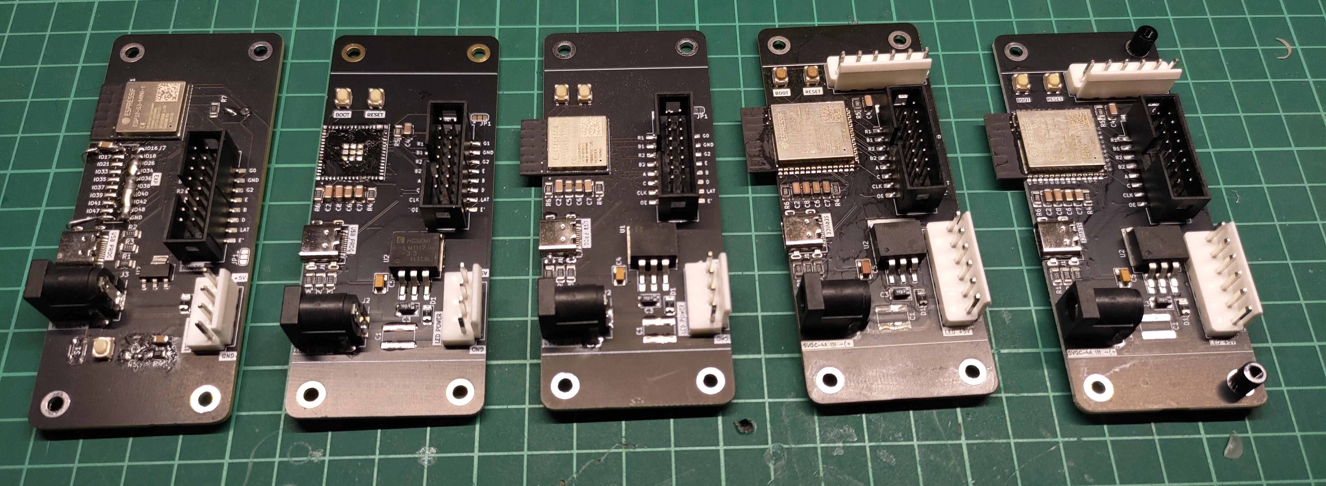
I order my PCBs from JLCPCB with a stencil and reflow them (in a converted Mio Star toaster oven) until I was sure everything is correct at which point I had JLCPCB assemble the boards for me.
As this board does have through hole components I have to add those myself after receiving them from JLCPCB.
Power
Power is an issue with these LED boards as they want 5V at quite a high amperage. I did not want to do any converting of voltages on the PCB for this first run so I opted for a 50W power brick with an extension. The unit won’t pull that much unless all LEDs are at full brightness and white which doesn’t happen in this case.
Software
There are several different stack required to make the thing work.
Firmware
This is what runs on the ESP32-S3 and has to be rock solid before I would ship. I can not have it crash randomly or brick once it leaves to the customer.
I also need to implement OTA or I would not be able to deal with issues in the future.
The firmware is still quite similar to the posted projects version but a lot of stuff has been removed as it done by the API backend.
Backend API
Initially the data was processed on the ESP32-S3 directly from the XML Api that Open data platform mobility Switzerland provides however this would require an API key for each device.
To deal with API limits I decided to implement my own backend API from which the ESP32-S3 can easily get what it needs without having to process it locally.
The initial idea was to use the same XML api und make calls up to the api limit. Using heavy caching of the data I was going to fudge a way to get enough users in order to pay for a higher limit which is expensive. I was going to require a subscription to get live data for the device.
I also implemented Open data platform mobility Switzerland GTFS format data. This allowed me to import the entire planned schedule and provide that for free to the end user.
After implementing the GTFS data I realized I could also implement the GTFS-RT (realtime) feed and avoid hitting any API limits. Although this was a lot of work the benefit to everyone not requiring a subscription was worth it.
Android and iOS App
The configuration of the devices out of the box had to be easily and doable by anyone with a phone. To achieve this, the only way I could think of was to provide a configuration app on android and ios.

To save time I build the whole thing in Capacitor (First time using it instead of native Android) using BluetoothLE to connect to the device and send configuration data to it which to my surprise worked very well.
Getting this particular app into the play and apple store is a bit of a pain because it requires recording a video of how it works since Google and Apple don’t have the device.
Feature creep
During the development and refinement of different parts you get ideas that you think would be cool to add. There is a risk however of feature creep and never finishing the product. I did implement some new things but held off on a lot to get it done. It is very easy to spend enjoyable hours on some new feature but it may not be what is needed to get a finished product. Although implementing new features isn’t really wasted time IMO it is still procrastinating and not doing what you are supposed to be doing.
Testing
The biggest thing here was to make sure that device doesn’t crash. Additionally I had to make the sure the API was correctly delivery the data.
I left several signs running for days and also checked the schedules against the SBB App. I did find a few bugs this way which I was able to fix.
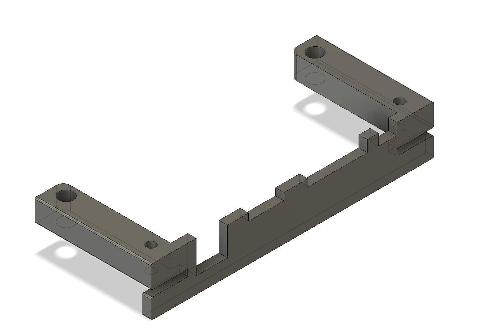
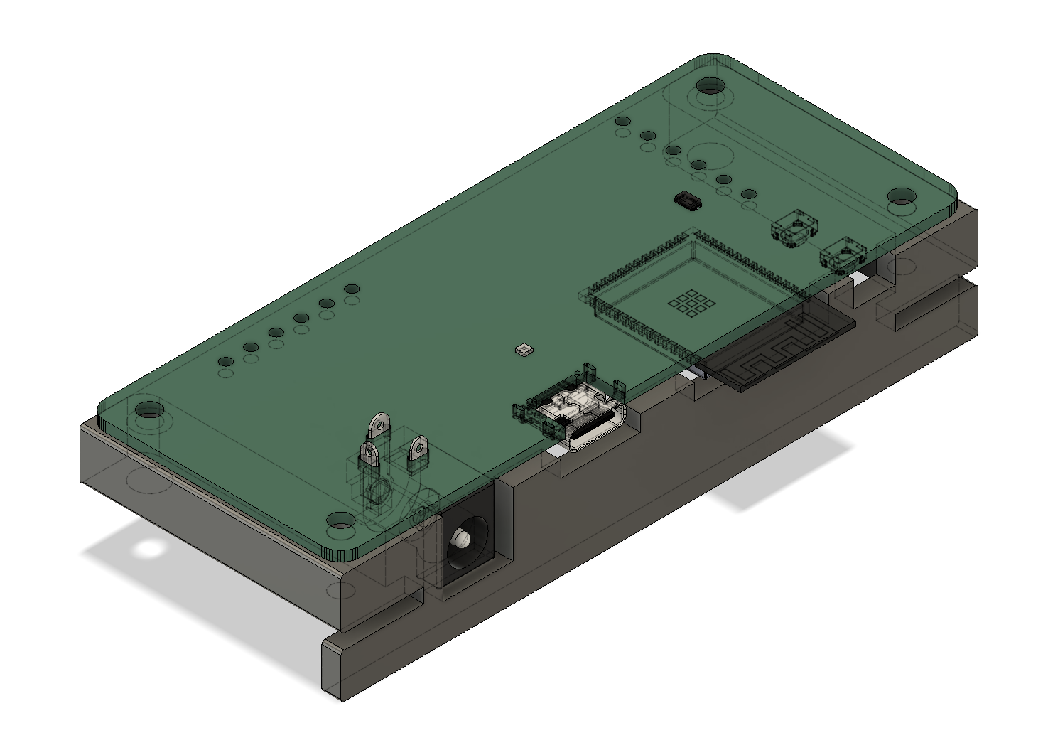
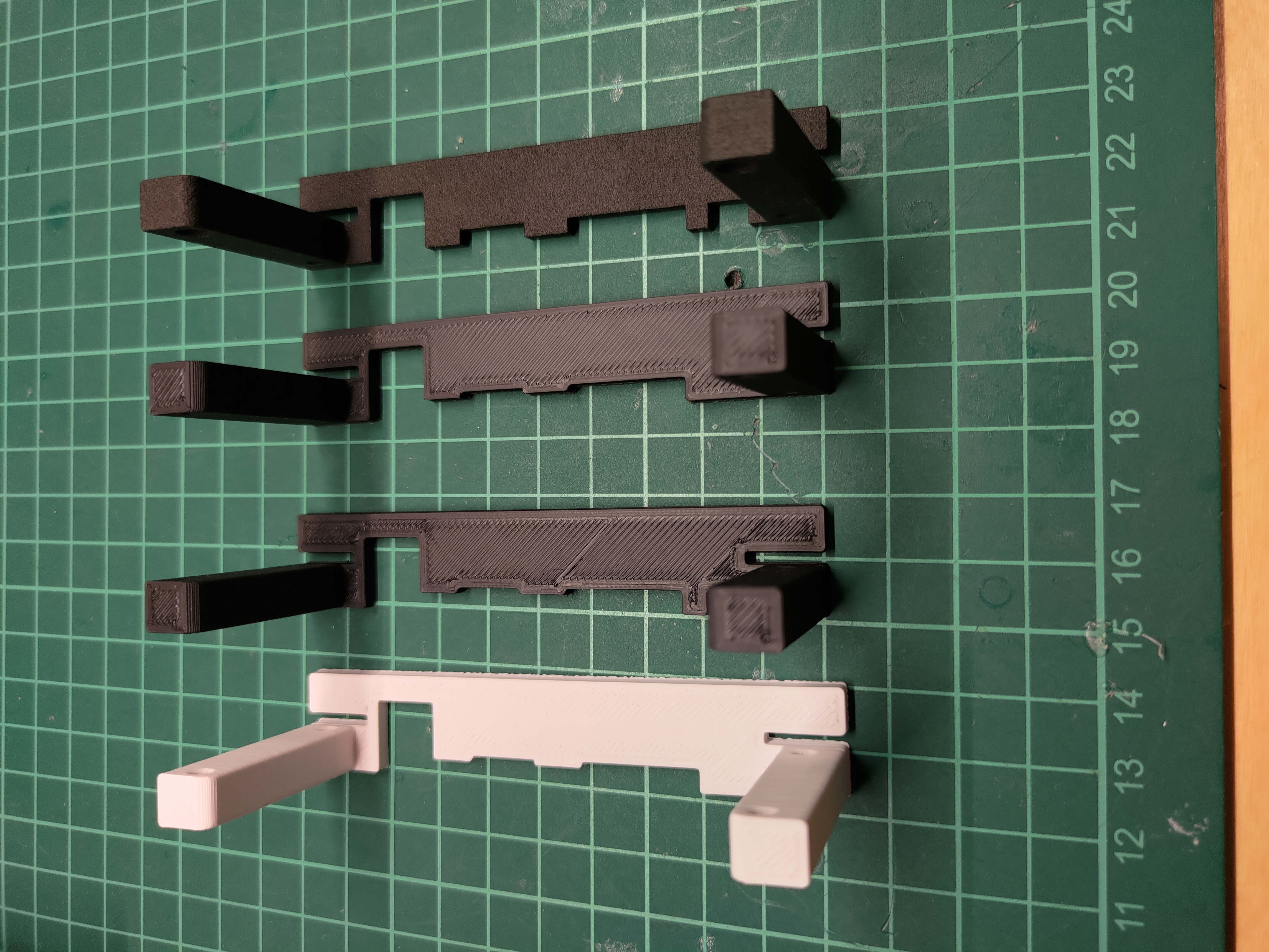
An issue that I was concerned about and noticed later was that the PCB is open on the sides. In order to avoid confusion as to where the power goes I created a 3d model that I could 3d print to protect the pcb from the side. The first few units have this part printed in ABS and later units I had this part 3d printed also by JLCPCB in Nylon.
Manufacturing & Assembly
As mentioned previously I had the PCB and assembly of the PCB done by JLCPCB. The frame was done by Blexon and the plexiglass was manufactured by ABC Kunststoff-Technik GmbH.
There is however still a significant amount of assembly I have to do. This includes the mounting of the PCB and LEDs in the frame, attaching the glass, crimping all the wires and programming the ESP32-S3.
Assembly Time LapseSales channel
As I don’t currently plan on selling a lot of these I did not spend much time on this other than the minimum necessary to sell a unit.
Website
A website if of course required to show what it even is and what the customer can expect. It is also a way for customer to contact me for support and find links to the app etc. On the website you will find a feature creep which is a JS version of the display to try out.
Photos
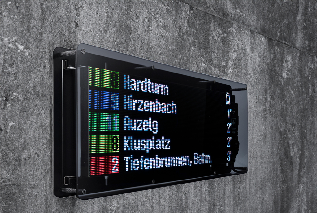
For the Photos I went with a local product photographer (Foto-Press) which I was very glad to have found as my attempts to photograph the sign were disastrous. It is very hard to photograph LEDs that have a specific refresh rate through a piece of plexiglass.
Webshop
The webshop is just an install of PrestaShop and the payment module for payrexx which is a Swiss payment provider similar to Stripe but supports Swiss payment methods such as TWINT.
Packaging & Shipping
For packaging I also went with something of the shelve as for so few units it does not make sense to have custom packaging made even though it would be very neat. I purchased standard boxes from Ratioform as well as lots of bubble wrap. If I were to have custom packing made I would want to use something that wouldn’t require plastic or styrofoam.
Conclusions
Issues I ran into that wasted a lot of time
- The ESP32-S3 does not log if you don’t set the correct compile flags unlike the S2.
- Getting the app in the app stores. Something I have quite a bit of experience with yet setting up a new account and convincing Apple and Google that your app is ok is a huge pain. I had to film videos of each app version together with the hardware or Apple and Google would reject my app as they can not “use” it. The new privacy policy you need to fill out at Google is ridiculous for the fact that I do not collect any data. At apple this was a simple checkbox. Additionally Apple accused me of not owning the rights to “Station Display” and therefore I can not mention “them” in my app description.
- Caching issues on the API side and the fact that the GTFS time table data goes over 24 hours if the trip belongs to the previous day.
- Finding ways to import large amounts of data into my database in a reasonable amount of time.
- The iOS simulator does not support bluetooth so it is not your code that isn’t working…
What would I do differently
- If this wasn’t just some experiment of mine and I wanted to create a real business I would do a lot of market research first to see what I can actually sell.
- Pre panelize the PCB for assembly by JLCPCB. This way I can for example move the JLCPCB tracking number outside of the PCB itself.
- Find a way to remove the through-hole components or get JLCPCB to assembly the through-hole components as well
- Have the cables manufactured so I don’t have the assembly them myself. I did ask a few vendors but they all require a larger order so this wouldn’t be sense unless I sell a lot of units.
- Possibly use an external antenna as the ESP32-S3 modules do not have the best wifi reception.
Possible future enhancements
If I sell more than a few I would be interested in adding more features which I decided not to include in this version or I would have never finished it. Some of those include:
- Add other countries/cities that have open GTFS data
- Possibly a USB-C powered version
- Outdoor version
Would I do it again
Yes. I learned a lot of new things and I had fun doing it.